By Ron Ruiz & William Pimblott
To read Part – 1 of this Three Part article, please click Here
Alrighty then; you’ve read Part – 1 of the article and have listened to the audio recordings of Direct Voice communication with the likes of Konstantin Raudive and others. You’ve browsed the report George Meek filed on his experience and saw the old Polaroid picture of the GA-1.
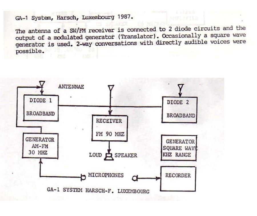
You’re probably wondering what was going on and how such a simple and inexpensive setup was able to establish contact with the other side. Well….let’s start by looking at an operational overview and block diagram of the GA-1 as written by Dr. Ernst Senkowski:
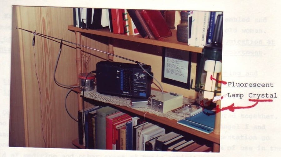
Now we can take another look at the GA-1 photograph George Meek took:
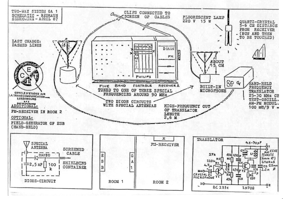
If you’re ready to get your geek on, here is the schematic of the GA-1 as drawn by Dr. Senkowski in April 1987:

For this next part of the article I called on William Pimblott to help me convey how Direct Voice communication might have occurred. Mr. Pimblott is an exceptional electronics technician, sound artist and long time technical advisor & moderator for ITCBridge & iDigitalMedium. William’s passion for building top of the line Ghost Boxes can be seen at his website: www.boutiqueghostboxes.com
Nuts & Bolts Of The GA-1
 Starting to understand the GA-1 begins with the radio. It is a Passat D-2225 made by Philips. This portable radio receives Medium Wave(AM) – FM – Short Wave 1/2 – Long Wave. It runs on batteries as well as house current. Radio reception is via the telescoping antenna. The radio was tuned to an off-broadcast FM channel between 87.5MHz to 90MHz.
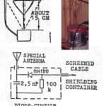 Jules and Maggy Harsch – Fischbach used two Raudive style diode receivers. As you know, this type of device is an un-tuned broadband crystal radio set. Its small antenna limits reception of radio signals to within a localized RF/EM field. A triangle shaped antenna is used for the input to the diode. As noted in the GA-1 schematic, the size of the diode antenna was increased slightly to improve reception. The output of the Diode Receiver was clipped to the antenna of the Radio. It should also be noted that in the photograph, only 1 diode receiver was in use at the time.
 An optional piece of equipment mentioned in the schematics and shown pictured in the photograph is the Field Generator. It was a contribution by ultrasound engineer Hans Otto Konig and featured a square wave oscillator / generator with an output of approximately 5KHz. Mr. Konig believed that square waves were more useful than sine waves in helping to establish contact with the folks on the other side.
In the photograph, the output of the Field Generator is clipped to the far end of the radio antenna. Unfortunately, there is no schematic showing the diagram of the generator so it is unclear if Konig used a standard oscillator circuit or perhaps some type of Schmitt Trigger variant. In any event, many square wave generator circuits can be found online with a simple search. They are also inexpensive to purchase.
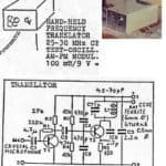 Another contribution to the GA-1 experiment from Hans Otto Konig was the Hand Held Frequency Translator. This nifty little device is a transmitter that provided a feedback loop to the radio. The diagram for the Translator shows a crystal (piezo) microphone input that takes in any signal / noise and modulates it in the FM range and spits the signal back out at 35MHz. A length of cable approximately 8 feet long was used to move the Translator around the room to try and find the optimal location for establishing contact. The output signal was also attached to the radio.
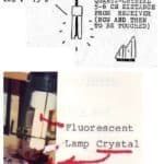 The last 2 components of the GA-1 were a 15 watt fluorescent lamp and a quartz crystal that one would occasionally touch. The quartz crystal was placed approximately 6 inches from the radio.
Turning on the GA-1 produced a Clash Of The Titans….so to speak….with sound
The radio comes on and sound is emitted by the speakers. Tuning to an off channel frequency produces white noise across a wide spectrum. As this white noise permeates the room, it reflects – refracts – deflects; bouncing off the walls – ceilings – furniture and people. While immeasurable in a small room, a tiny time delay in sound occurs from secondary reflections.
Additional high frequencies around 25KHz are injected by the flicker fusion of the fluorescent lighting. Although the lamp mainly produces white light, some Ultraviolet light is emitted. A piezoelectric effect from all the frequencies causes the quartz crystal to vibrate ever so slightly.
The Diode Receivers begin picking up on the EM / RF field being created and sends its own weak output signal to the radio’s antenna. Meanwhile, the 5KHz Field Generator feeds an additional chirping noise to the radio, causing even more sound output.
And Then….
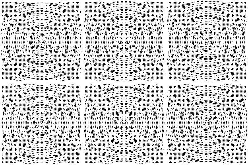 The handheld Frequency Translator does its thing by creating a feedback loop. Remember, the Translator has a microphone that is picking up all that sound in the room, modulating it and sending it back out to the radio which in turn incorporates the signal and sends everything back out through the speaker. Multi-Phonics flood the room with an infinite loop of frequency vibrations. Square waves and sine waves battle for supremacy.
And Then….Magic….
As the constant outpouring of noise persists, frequencies collide within the room. Noise cancellation begins as exact frequencies meet. The Uber Duber Super Duper Pièce de Résistance of the GA-1 materialize as beat frequencies assault your senses. Most of you are familiar with Binaural Beats but what you might not know is that beat frequencies happen across the spectrum as 2 wave tones interfere with each other and create a third beat frequency.
Heterodyning from the feedback loop helps the EM cause by the frequency modulation of the Translator. This transfer happens by mixing the original speaker output of the radio with the Translator’s re-modulated output of 35MHz. This process produces a beat frequency equal to the difference between the frequencies, causing a third carrier which will be modulated again by the original signal. Have to love those feedback loops.
With an 8 foot cord, Jules and Maggy Harsch Fischbach needed only to move the Translator around the room until they found the optimal dynamic. Out of this seething soup of sound, conditions became ripe for trans-communication to take place.
With the additional psychic connection of Jules and Maggy, the GA-1 was manifested into physical form….materialized in part by the raw sound. While their exact psychic components are unknown, we at least have the basis for a Trans-Dimensional Alchemical Flowchart.
We hope you have enjoyed Part-2 of this 3 part series. In the next article of the Euro Signal Bridge of Jules and Maggy Harsch Fischbach, we will cover the video capabilities of the ESB.
~ Ron Ruiz & William Pimblott
