By Ron Ruiz & William Pimblott
To read Part – 1 of this three part article, please click Here
For Part – 2; Please click Here
Alrighty then; you’ve read Part – 1 of the article and have listened to the audio recordings of Direct Voice communication with the likes of Konstantin Raudive and others. You’ve browsed the report George Meek filed on his experience and saw the old Polaroid picture of the GA-1.
In Part – 2, you gained an understanding of how feedback loops and beat frequencies can promote conditions ripe for Trans Dimensional communication.
In this last article, we will show you the flip side of Jules and Maggy Harsch Fischbach’s Euro Signal Bridge. We’re talking Video 😉
Somehow – Somewhere along the way, The Fischbach’s were prompted to try receiving video images. Through trial and error, along with the generosity of Hans Otto Konig, they finally settled on an assembly of equipment that proved very promising.
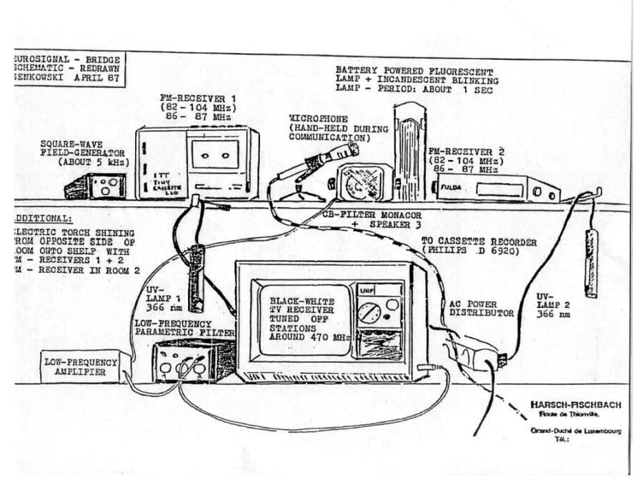
Here is the ESB diagram which operated in tandem with the GA-1 in 1987:
Here is the operational overview and block diagram provided by Dr. Ernst Senkowski in 1986:
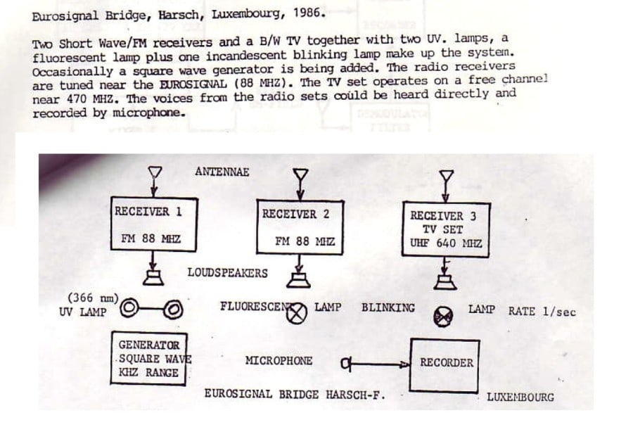
In reading the operational overview, it is clear the ESB was the prototype predecessor to the GA-1. Jules and Maggy Harsch Fischbach used the ESB for Direct Voice communication. With the help from their “Technician” on the other side, instructions were provided on how to assemble the GA-1.
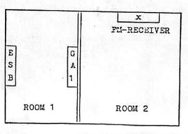
The TV – labeled Receiver #3 was placed in a separate room as noted in the room schematic shown below:
 Because I have no photograph of the ESB or connections of FM Receivers 1 & 2, I will have to make the assumption that the FM receivers operated independently from each other.
 Looking at the ESB Diagram, on the top shelf, on the left we see Hans Otto Konig’s Square Wave Generator that spit out square waves at approximately 5 Kilo Hertz. This optional piece of equipment was used both on the ESB as well as the GA-1.
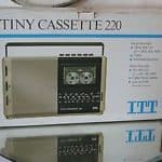 To the right of the Square Wave Generator, we have FM Radio #1 – an ITT Tiny Radio Cassette combo model 220. This multi-Band radio was tuned to an off channel near the FM Euro-Signal of 88 Mega Hertz.
Next to FM Radio #1, a dynamic microphone is shown. This microphone was plugged into FM Receiver #2.
To the right of FM Radio #1 is an army surplus battery powered fluorescent light (white light). Noted, but not pictured was a second, Incandescent Light which blinked at a rate of Once Per Second. The two lights were placed opposite of each other so each light’s output frequencies could interact with each other. The reason for the blinking light was for Spirit to use as a coordinating Timing Device for communication.
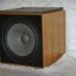 Next up is a Monacor brand Bass speaker similar to the thumbnail picture. The speaker was connected to the output of a low frequency amplifier.
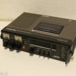 FM Receiver #2 is a bit of a mystery. Dr. Senkowski lists it as an FM Receiver; however the device is labeled as a Philips D6920 – which is a portable cassette recorder. Since the dynamic microphone was plugged into it, I will assume it was used to record sessions.
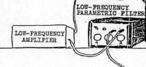 Looking at the bottom shelf of the diagram, on the left we find a Low Frequency Amplifier that powered the Monacor speaker. The input of the Amplifier was fed directly from a Low Frequency Parametric Filter.
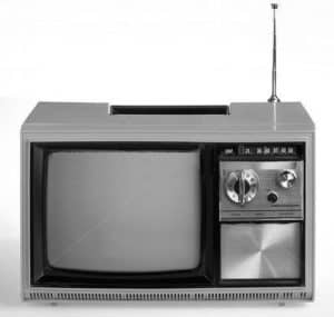 To the right of the Amplifier and Parametric Filter was a 1960’s era Universum Portable TV. During the Fischbachs’s experiments, it is noted the TV’s antenna was broken off to the point where no local stations could be received. The tuning for the TV varied from Channels 21 – 35 – 40 & 60. The audio out from the TV was fed into the input of the Parametric Filter.
From an audio standpoint, the basic principle of taking the TV’s audio into the Parametric filter and then using the Low Frequency Amplifier to power the Monacor Bass Speaker was to enhance the Infrasonic Modulation of the selected TV channel to further promote Direct Voice communication.
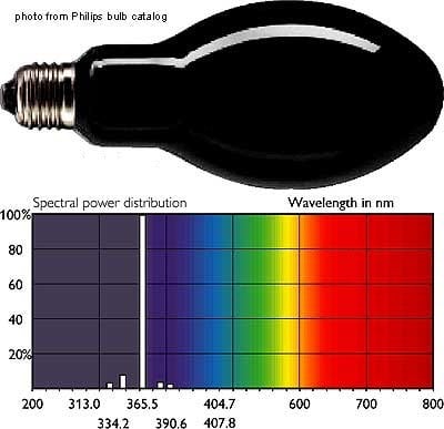 If you notice the drawing, you will see that 2 Philips OSRAM HQV 125 Watt Mercury Vapor Ultraviolet lamps were used. These UV lights had an output wavelength of approx 366 Nano Meters.
But wait…………..
While you have an idea of the equipment array of the ESB, the process that obtained the iconic video images that Jules and Maggy captured were different than the drawing suggests. Remember the room diagram?
According to the book Bridge between the Terrestrial and the Beyond – Theory and Practice of Transcommunication -by Hildegard Schaefer, the setup used for capturing video is as follows:
The ESB and GA-1 were in one room doing their audio thing along with the blinking light used for timing.
The TV with the broken antenna was in an adjoining room. The Ultraviolet lamps with aluminum foil reflectors were placed on the floor at an oblique upward angle 3 feet from the TV.
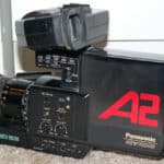 With the TV set turned on and set to Channel 35, a Panasonic A2 Video Recorder was positioned approx 6 1/2 feet in front of the TV. Unlike the Klaus Schreiber method, The images captured by the Fischbach’s were full screen as opposed to a video feedback, zoomed corner of the TV screen.
Here are a couple of examples of video the Fischbach’s captured during their experiments.
This first clip is said to be the image of a now young EVP researcher Hanna Bushbeck who died at the age of 70. The woman appears to move her lips as if to speak. You will hear the low rumble of the ESB in the background as Jules reviews the footage frame by frame.
In this second clip which was recorded on May 2, 1987 while George Meek was in Luxembourg visiting, we see an image said to be the face of 19th Century chemist Henry Etienne Ste. Claire Deville who turns his head slightly. Other images include still images of three or four people sitting around a table, a landscape scene and a very quick segment of a person walking on the beach.
To see more images and information on Jules and Maggy Harsch Fischbach’s experiments, please visit Mark Macy’s epic website: worlditc.org
It should be stated that the Fischbach’s were only able to capture images for a short while. The last time images came through the ESB/GA-1 was late December 1987.
After that it seems our friends on the other side had an interest in new technology because they started communicating via the Fischbach’s computer. But that is another story for another day. 🙂
William Pimblott and I thank you for your time and we hope you’ve come away with a better understanding of the Euro Signal Bridge of Jules and Maggy Harsch Fischbach.
Peace…
